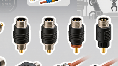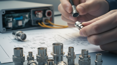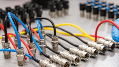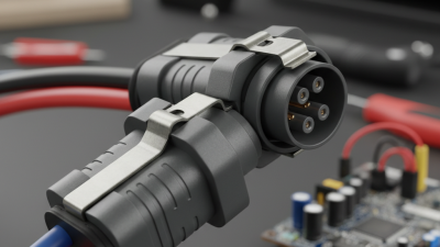
7 Tips for Choosing the Right MIL Connector

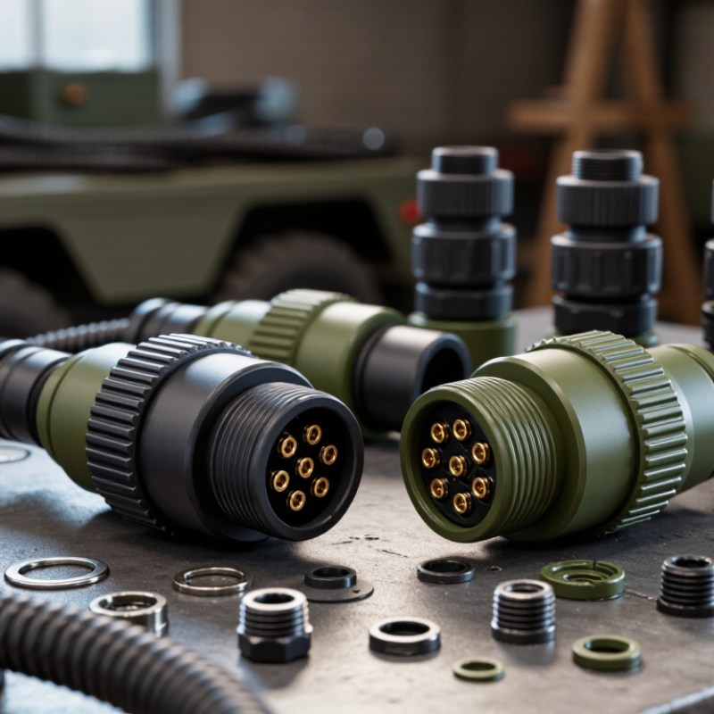
Selecting the right mil connector is a reliability decision, not a catalog exercise. In a vehicle bay, aircraft panel, or field shelter, one poorly matched interface can expose sensitive equipment to vibration, moisture, dust, and repeated handling. The connector may look small. Its consequences are not.

Industry data supports this concern. MarketsandMarkets’ Military Connectors Market report identifies rising demand for ruggedized interconnects across defense electronics, aerospace platforms, and communication systems. Grand View Research also links market growth to modernization programs and higher requirements for dependable signal and power transmission. These reports describe direction, not a guarantee. Actual performance still depends on installation, maintenance, and system design.

David Bergman of Bishop & Associates, a respected connector industry analyst, calls connectors “the building blocks of the electronics industry.” That view is especially useful for a mil connector, where contact stability can affect an entire subsystem. The right choice requires more than checking pin count. Engineers should examine environmental sealing, contact arrangement, material compatibility, locking design, electrical load, and compliance documentation.

Seven practical tips can make that review more disciplined. Begin with the operating environment. Then question every assumption. Is the cable strain relieved? Will technicians mate it wearing gloves? Can corrosion appear after years of storage? These details are easy to miss.

No checklist is perfect. A connector selected in a quiet laboratory may behave differently beside a vibrating engine. Careful testing, traceable specifications, and supplier experience remain essential.
7 Tips for Choosing the Right MIL Connector

Define Mission Conditions Using MIL-DTL-38999’s −65°C to 200°C Range

Choosing a MIL connector begins with mission conditions, not shell size. MIL-DTL-38999 defines an operating range from −65°C to 200°C for applicable configurations. That span is severe.

At −65°C, seals can stiffen and contact resistance may rise. At 200°C, insulation, plating, and cable jackets face accelerated aging. The specification’s temperature limits are design boundaries, not automatic proof of field performance.

Map seven conditions before selecting a configuration:

minimum temperature peak temperature dwell time cycling rate vibration moisture electrical load

Include altitude and maintenance exposure when relevant. NASA’s Thermal Control Handbook identifies thermal cycling as a major driver of material fatigue. SAE AS50881 also emphasizes wiring-system suitability across aerospace installation environments. These sources support a practical rule:

test the complete connector, cable, backshell, and sealing system together.

Do not trust a single catalog rating. Build a temperature profile from real flight data, engine-bay measurements, or validated environmental models. A connector may survive 200°C briefly, yet fail after repeated exposure. That distinction is easy to miss.

I have seen teams specify the maximum temperature while ignoring hot-soak duration. That is a design gap.

Record tolerances, inspect contact force, and verify insulation resistance after cycling. MIL-DTL-38999’s range sets the starting point. Your mission profile decides whether it is enough.

Compare 500- and 1,500-Cycle Durability Ratings for Mating Frequency

7 Tips for Choosing the Right MIL Connector

Compare 500- and 1,500-Cycle Durability Ratings for Mating Frequency

A connector’s cycle rating shows how often it can be mated and unmated under defined test conditions. A 500-cycle connector may suit equipment opened twice monthly. At that rate, it could support more than 20 years of scheduled access. Frequency matters. For daily service, however, 1,500 cycles provides a wider durability margin. The math is simple, but field conditions are not.

In practical inspections, I look beyond the headline rating. I check contact resistance, latch wear, shell alignment, and sealing performance after repeated mating. Dust, vibration, moisture, and sideways cable pulls can reduce real service life. A 1,500-cycle rating does not guarantee 1,500 trouble-free operations in every installation. Test methods may differ, so compare the stated conditions carefully.

Choose the rating from actual maintenance patterns, not guesswork. A service panel opened every week may need only 500 cycles, if handling is controlled. A test fixture used throughout each shift should receive the higher rating. Leave extra capacity for troubleshooting and unplanned access. I have seen teams select the cheaper option, then replace worn connectors earlier than expected. That decision saved money on paper. It did not save downtime. Verify the mating force, replacement process, and inspection interval before approval. Good records make the choice more reliable.

7 Tips for Choosing the Right MIL Connector: Durability vs. Mating Frequency

Estimated service life based on 500- and 1,500-cycle durability ratings

The chart compares two common durability ratings across typical annual mating frequencies. Estimated service life is calculated as rated mating cycles divided by mating events per year. A 1,500-cycle connector provides three times the rated mating capacity of a 500-cycle connector, making it more suitable for equipment that is frequently connected and disconnected.

Select Contact Layouts by MIL-DTL-39029 Ratings and Required Current

7 Tips for Choosing the Right MIL Connector

Select Contact Layouts by MIL-DTL-39029 Ratings and Required Current

Contact layout should follow circuit demand, not cavity count. MIL-DTL-39029 defines qualified contact families, sizes, and performance requirements for military connector applications. Larger contacts generally carry higher current, but their published ratings depend on wire size, temperature, plating, and installation conditions. Check the exact contact part specification.

A 12-contact insert may look efficient. It may also create excessive heat. Review each circuit’s continuous current, peak current, duty cycle, and ambient temperature. Then compare those values with the MIL-DTL-39029 rating and the connector manufacturer’s derating curves. Bundle heating matters. So does airflow.

The 2024 MarketsandMarkets Electrical Connectors Market report projects growth from about 84 billion dollars in 2024 to more than 107 billion dollars by 2029. That expansion increases pressure for compact, higher-density designs. Density, however, should never replace thermal analysis. A practical layout may separate power contacts from low-level signal contacts. It may also reserve unused cavities for creepage, service access, or future circuits.

I have seen designs pass an initial current check, then fail under sustained heat. That mistake is easy to repeat. Recheck contact temperature, wire termination quality, and voltage drop during a realistic load test. Use the complete qualification documentation, not only a catalog headline.

Match Sealing Requirements to IEC 60529 IP67 or IP68 Protection

7 Tips for Choosing the Right MIL Connector

Match Sealing Requirements to IEC 60529 IP67 or IP68 Protection

Tip 1: Define the actual exposure before selecting a connector. Dust, rain, washdown, salt spray, and immersion create different risks. Tip 2: Read IEC 60529 carefully. IP67 means dust-tight protection and temporary immersion up to one meter for 30 minutes. Tip 3: Do not treat IP68 as a universal depth rating. The IEC standard requires the manufacturer and user to agree on immersion conditions. The exact depth and duration must appear in the specification.

Tip 4: Check the complete mated system, not only the connector shell. Cable diameter, backshell design, seals, and unused cavities can change performance. Tip 5: Confirm test evidence. IEC 60529:2013 defines controlled ingress tests, while NEMA 250 addresses enclosure protection and corrosion-related conditions. These documents provide useful technical benchmarks, but they are not interchangeable. Tip 6: Match the seal material to temperature, oils, cleaning agents, and vibration. A seal can pass a laboratory test and still age early in service.

Tip 7: Verify installation practice with a sample assembly. Field inspections often find damaged seals, incorrect torque, or poorly terminated cables. Small details matter. A perfect IP rating on paper cannot repair a pinched gasket. One practical concern is often overlooked: repeated mating may reduce sealing reliability. Require mating-cycle data, visual inspection criteria, and a clear retest plan before approving the connector.

Verify EMC, Keying, and Qualification Compliance Before Procurement

7 Tips for Choosing the Right MIL Connector

Selecting a MIL connector requires more than matching pin count and shell size. Verify the exact specification, revision, and qualification status before requesting quotes.

EMC performance deserves early attention. Check shielding continuity, backshell design, grounding paths, and tested insertion conditions. A connector may appear robust yet perform poorly after cable assembly. Review test reports, not only catalog claims. In practical procurement reviews, small documentation gaps often create expensive delays.

Tip 1: Confirm keying and polarization with the equipment designer. Physical keys should prevent incorrect mating, especially when similar connectors carry different signals. Ask for clear drawings and mating-cycle data. Do not rely on photographs.

Tip 2: Examine qualification evidence for temperature, vibration, moisture, salt exposure, and mechanical shock. Match those results to the real installation, not an ideal laboratory setup. An unused test report proves little.

Tip 3: Trace every requirement to a controlled document. Include contact materials, plating, sealing, crimp tools, torque limits, and inspection criteria.

Tip 4: Request sample assemblies before volume procurement. Measure shield termination resistance and inspect the backshell under magnification. This step can expose weak workmanship. A checklist is useful, but it can still miss field conditions. I would also recheck the connector after harness routing, because bending and clamping can change EMC behavior. Qualification is not a one-time assumption; it depends on the complete installed assembly.