Global power systems are becoming denser, faster, and less tolerant of connection failures. The International Energy Agency’s Global EV Outlook 2024 reports that electric car sales exceeded 17 million in 2024, increasing demand for dependable high-current charging hardware. At the same time, the Uptime Institute’s data center surveys continue to identify power distribution and component failure as serious operational concerns. These trends make connector selection a practical engineering decision, not merely a purchasing task.
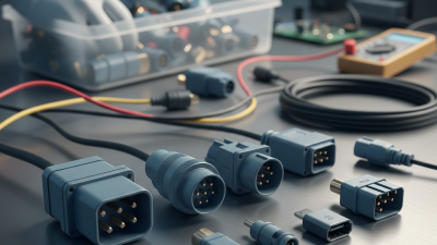
This guide examines top amphenol powerlok connectors for global buyers, focusing on current capacity, locking design, sealing, cable compatibility, and installation conditions. Amphenol’s PowerLok family is widely considered for battery systems, electric vehicles, charging equipment, energy storage, and industrial power distribution. Exact performance depends on the selected series, cable size, temperature range, and mating configuration. Check the datasheet carefully.
A connector may look small, yet it can carry substantial energy beside hot batteries, vibrating equipment, or exposed outdoor cabinets. That detail matters. Reports from MarketsandMarkets on EV charging infrastructure and energy storage indicate continued expansion in high-power electrical systems, but market growth does not remove engineering risk. No single PowerLok model fits every project.
Buyers should verify contact ratings, ingress protection, touch safety, approvals, and supply continuity before ordering. Regional certification requirements may also affect deployment. A polished comparison can still overlook field conditions. Therefore, this article combines product-focused analysis with practical procurement questions, helping engineers, distributors, and international buyers make more defensible connector decisions.
High-voltage connector architecture now matters as much as current capacity. The International Energy Agency reported over 14 million electric cars sold worldwide in 2023. That growth increases demand for safer, faster service connections. A 1,000 V DC design can reduce current for the same power, but insulation, creepage, and sealing become more demanding.
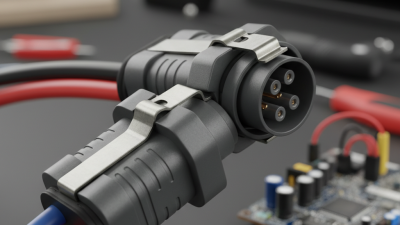
HVIL creates an independent low-voltage monitoring loop. It confirms that the connector is fully seated before high voltage becomes available. If the latch opens, the system should command contactors to disconnect power. Touch-safe interfaces add another physical barrier. Shrouded contacts, recessed terminals, and secondary locks help prevent accidental contact during inspection.
Small details matter.
Field engineers should check HVIL continuity, contact resistance, and locking force during commissioning. The connector should also tolerate vibration, moisture, thermal cycling, and repeated service operations. The IEC 60664 insulation-coordination framework highlights the importance of clearance and creepage under working-voltage conditions. However, a rating label alone proves little. Installation quality can change real performance.
The IEA Global EV Outlook 2024 also shows rapid expansion of charging infrastructure, making interoperability and maintenance increasingly important. A connector that feels secure may still have damaged seals or incomplete terminal engagement. That uncomfortable possibility deserves attention. Buyers should request test evidence for 1,000 V DC operation, HVIL behavior, touch protection, and environmental endurance before approving a global supply.
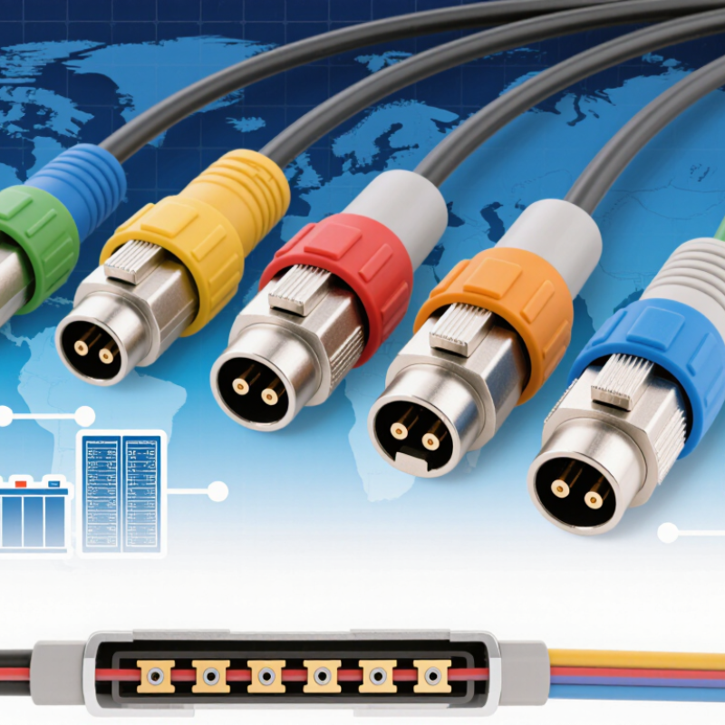
The chart compares representative high-voltage DC system classes used in electric and industrial equipment. A 1,000 V DC rating provides additional design headroom above common 400 V and 800 V platforms. HVIL circuits help verify that the connector is fully mated before high voltage is enabled, while touch-safe construction helps prevent access to energized contacts.
Top Amphenol PowerLok Connectors for Global Buyers
High-current connectors are often selected by headline rating alone. That approach can create expensive surprises. A 120 A configuration suits compact battery packs, auxiliary drives, and moderate industrial loads. It usually allows smaller cables and simpler routing inside crowded enclosures. However, continuous current depends on ambient temperature, conductor size, contact resistance, and ventilation.
The 300 A class offers a practical middle ground. It fits traction equipment, charging systems, and heavy-duty power distribution. At this level, terminal crimp quality becomes critical. A poorly compressed crimp can heat during sustained operation, even when the calculated load appears acceptable. I have seen installation teams check voltage drop but overlook connector temperature. That mistake deserves more attention.
A 500 A configuration supports demanding applications, including high-power vehicles and stationary energy systems. It needs robust busbars, secure locking, and carefully controlled cable bending. Peak current is not the same as continuous current. A connector may tolerate a short surge but require derating during long operation. Buyers should compare test conditions, mating cycles, sealing performance, and regional certification requirements. Datasheet figures can look precise. Real installations are messier. Verify every assumption before finalizing the design.
| Comparison Dimension | 120 A Configuration | 300 A Configuration | 500 A Configuration |
|---|---|---|---|
| Nominal Continuous Current | 120 A | 300 A | 500 A |
| Illustrative Power at 400 V DC | 48 kW | 120 kW | 200 kW |
| Typical Conductor Cross-Section | Approximately 25–35 mm² | Approximately 70–95 mm² | Approximately 120–150 mm² |
| Common System Voltage Range | Up to approximately 800 V DC, subject to connector design | Up to approximately 1,000 V DC, subject to connector design | Up to approximately 1,000 V DC, subject to connector design |
| Typical Application Areas | Battery modules, compact industrial equipment, auxiliary power distribution, and charging subsystems | Energy-storage cabinets, industrial inverters, electric commercial vehicles, and high-power charging equipment | Large battery systems, heavy-duty vehicles, grid-storage equipment, and high-power DC distribution |
| Thermal Management Consideration | Natural cooling is often practical when ambient temperature and duty cycle are controlled | Conductor bundling, enclosure temperature, and continuous-duty loading require detailed thermal evaluation | Forced-air cooling, liquid cooling, or strict duty-cycle control may be required for continuous operation |
| Voltage Drop Sensitivity | Moderate; cable length and conductor resistance should be reviewed for long runs | High; low-resistance conductors and short cable routes are generally preferred | Very high; busbar layout, parallel conductors, contact resistance, and cooling are critical |
| Recommended Protection Strategy | Use appropriately rated fuses or circuit breakers with overcurrent and short-circuit protection | Coordinate high-current fuses, contactors, pre-charge circuits, and system-level fault interruption | Use engineered high-current protection, isolation monitoring, pre-charge control, and rapid fault interruption |
| Mating and Service Priorities | Compact size, touch-safe design, keying, and straightforward field installation | Robust locking, vibration resistance, high-cycle durability, and clear cable routing | Secure locking, mechanical strain relief, controlled mating force, service isolation, and thermal monitoring |
| Environmental Design Checks | Confirm sealing, temperature range, vibration resistance, and corrosion protection for the installation | Verify ingress protection, shock and vibration performance, salt mist resistance, and cable-bend limits | Verify enclosure sealing, thermal derating, vibration endurance, creepage and clearance, and service access |
| Global Specification References | Review applicable requirements for low-voltage equipment, touch protection, cable assemblies, and ingress protection | Review applicable requirements for industrial connectors, high-voltage interconnection, EMC, and environmental testing | Review applicable requirements for high-current DC systems, insulation coordination, thermal performance, and fault protection |
| Best Selection Priority | Space efficiency, moderate power demand, and easy installation | Balanced power density, durability, and manageable thermal performance | Maximum power transfer, low contact resistance, thermal control, and engineered system protection |
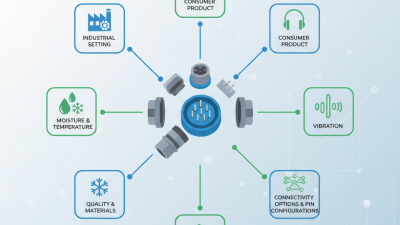
For global buyers, PowerLok-style connectors should be judged by protection details, not appearance alone. An IP67 rating indicates resistance to dust and temporary water immersion when the connector is fully mated. IP6K9K goes further, addressing high-pressure, high-temperature water jets used in demanding vehicle and industrial cleaning areas. These ratings apply to the complete assembled interface, including seals, backshells, and protective caps.
A practical inspection starts with the sealing face. Look for an even gasket, clean contact surfaces, and firm locking engagement. A small seal twist can create a leak path. Cable routing matters too; sharp bends may stress the rear seal during vibration. In field evaluations, repeated washing often exposes weak assembly habits before the connector itself fails. The environment is rarely gentle.
Ten thousand mating cycles sounds impressive, but the number needs context. Test speed, load, lubrication, alignment, and contamination can change the result. Dust on a guide pin may increase insertion force over time. Operators should record cycle counts and inspect terminals for wear instead of trusting a label. Some installations never approach 10,000 cycles, while service equipment may exceed expectations quickly. That difference deserves attention.
Global buyers selecting high-current locking connectors should start with cable size, not housing shape. The IEA’s Global EV Outlook 2024 reports more than 14 million electric cars sold in 2023. It expects sales to exceed 17 million in 2024. This growth increases demand for compact, high-power cable systems.
A 35 mm² cable may carry different current in open air, conduit, or a tightly bundled harness. Check continuous current, peak load, voltage drop, and derating together. Many systems require operation from -40°C to 125°C. However, terminal heating can reduce the practical margin. Field experience shows that a connector can remain within its rating while the nearby cable insulation ages early. That detail is easy to miss.
EMC performance also depends on the cable shield and backshell interface. A short drain wire may pass basic checks, yet perform poorly near an inverter. Use a continuous 360-degree shield termination where possible. Validate the assembly against IEC 60512 tests and CISPR 25 vehicle-emission methods. The standards guide testing, but installation quality decides the result.
Tips: Request current-versus-temperature curves, not only headline ratings. Measure the cable bundle at its hottest point. Leave room for gloves and inspection. I once trusted a generous catalog rating too quickly; the field temperature proved my assumption incomplete.
High-voltage connector selection starts with evidence, not appearance. USCAR-2 evaluation should cover terminal retention, vibration, temperature cycling, sealing, and contact resistance. These tests reflect real vehicle conditions, including engine-bay heat and repeated service movement.
ISO 19642 is also important for cable compatibility. It defines requirements for automotive high-voltage cables, including electrical performance, insulation, dimensions, and environmental durability. The connector, cable, shielding, and crimp must work as one system. ISO 6469-3 and UNECE R100 add safety expectations for electric powertrains, especially insulation, protection against electric shock, and isolation monitoring. The International Energy Agency reported nearly 14 million electric car sales in 2023. That growth increases pressure on suppliers to provide repeatable, documented compliance. Still, standards alone do not guarantee field reliability. Test fixtures, mating cycles, and production variation can expose weak points.
Tips: Request full test reports, not only certificates. Check test temperatures, sample quantities, and failure limits. Confirm whether results apply to the exact cable size and plating. A visually perfect connector may still have unstable crimp resistance. My practical concern is simple: many purchasing teams compare ratings, but overlook service access and repair procedures. That gap deserves review.