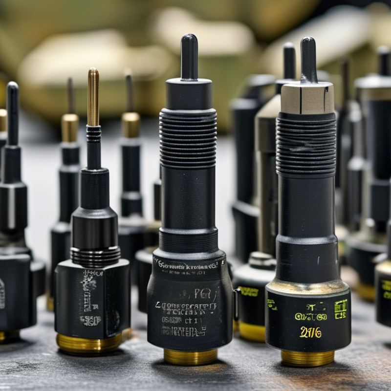
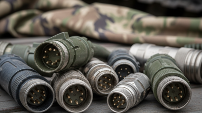
Choosing amphenol military connectors in 2026 requires more than matching pin counts and shell sizes. It requires evidence from harsh operating conditions. A connector may face vibration inside an armored vehicle, salt mist near a naval deck, or repeated mating during field maintenance. MarketsandMarkets’ Military Connectors Market report indicates continued growth through the decade, driven by defense electronics, unmanned systems, and modernization programs. Fortune Business Insights reports a similar expansion trend. However, market forecasts vary because definitions and regional coverage differ. That uncertainty deserves attention.
R. Adam Norwitt, Amphenol’s former chief executive, described the company’s purpose as “enabling the future.” That phrase matters here. The right amphenol military connectors must enable reliable power, signal, and data transmission without creating a hidden maintenance burden. Buyers should examine MIL-DTL qualification, sealing performance, contact materials, electromagnetic compatibility, temperature range, and lifecycle support. The U.S. Defense Logistics Agency’s Qualified Products Database can help verify approved products, while supplier test reports reveal details that catalogs often simplify.
Look beyond the label.
A compliant connector is not automatically the best connector for every platform. Installation space, cable routing, torque control, and technician access can change the decision. I have seen specifications appear complete while omitting backshell strain relief or corrosion exposure. That is a costly gap. A defensible 2026 selection process combines manufacturer documentation, independent testing, field experience, and careful review of the actual mission environment. Perfect certainty is unrealistic, but disciplined evidence makes failure less likely.
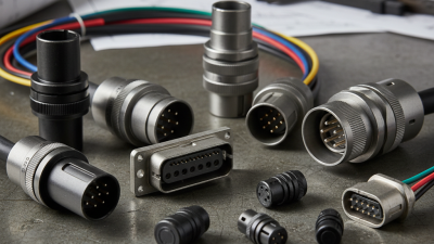
Military connectors come in several practical forms: circular, rectangular, board-to-board, and fiber-optic designs. Circular versions suit vehicles, radios, and field equipment because threaded or bayonet couplings resist vibration. Rectangular connectors support dense avionics wiring. Fiber-optic types handle high-bandwidth data and avoid electromagnetic interference.
Key features matter more than appearance. Check contact count, voltage rating, temperature range, sealing level, and shell material. Locking systems should remain secure beside engines or rotating machinery.
Gold-plated contacts can improve corrosion resistance, but they do not solve poor assembly. Field experience shows that backshell design often receives too little attention. It controls cable strain and may determine long-term reliability.
Grand View Research estimated the global military connector market at about USD 3.2 billion in 2023, with continued growth expected through 2030. MarketsandMarkets also identifies ruggedization, miniaturization, and high-speed data transmission as major demand drivers. These trends favor lighter connectors with stronger environmental protection. However, choosing the smallest option is not always wise. Maintenance access can become difficult. Verify performance against relevant military specifications, including sealing, shock, vibration, and salt-spray requirements. A connector that passes laboratory testing may still fail after repeated mating in dust, rain, or cold conditions. Document the selection criteria, test evidence, and supplier traceability before approving the design.
Connector selection should begin with measured electrical demands, not a familiar part number. Record operating voltage, continuous current, peak current, and circuit frequency. Leave realistic margin for startup surges and future upgrades. A connector rated exactly at the limit may become unreliable under heat.
Signal circuits need separate attention. Check impedance, crosstalk, shielding, and contact resistance. High-speed data can fail even when power tests look normal. Confirm the wire gauge, termination method, and required mating cycles. I have found that a small mismatch between contacts and cable can create intermittent faults during vibration.
Environmental requirements must describe the real installation. Note temperature extremes, humidity, dust, fluid exposure, shock, vibration, and altitude. A sealed connector is not automatically suitable for every environment. Verify its ingress rating after mating, servicing, and cable bending. Corrosion resistance also matters near salt spray or industrial chemicals.
I once underestimated condensation inside an enclosure. The connector passed bench testing, yet failed after repeated temperature changes. That mistake changed our test plan. We now include thermal cycling, insulation resistance checks, and visual contact inspections. Do not ignore installation space, keying, retention force, or field-repair needs. A technically capable connector may still be the wrong choice if technicians cannot mate it with gloves. Performance data should come from current technical documentation and controlled testing, not assumptions.
Military connector selection starts with materials, not catalog shape. Aluminum shells reduce weight, while stainless steel offers stronger abrasion and corrosion resistance. Composite shells can lower mass further, but field repair may be less convenient. MarketsandMarkets’ 2024 military connectors report projects the sector to grow at roughly 6% annually through 2028. That growth reflects harsher platforms and higher data demands. It does not make every lightweight option suitable.
Contact material also changes long-term reliability. Gold-plated copper alloys provide stable conductivity and resist oxidation. Silver contacts can perform well at high current, but tarnish control deserves attention. For vibration-heavy systems, specify contact retention, normal force, and mating-cycle data. The U.S. Department of Defense’s connector qualification documents emphasize environmental sealing, vibration, thermal shock, and salt exposure. Laboratory figures are useful. They can still miss a muddy maintenance bay.
Tips: Match the contact size to current, voltage, and signal frequency. Choose crimp terminations for repeatable field repairs and strong strain relief. Solder terminations may suit controlled assembly, but workmanship varies more. Board-mount versions save space, yet thermal expansion can stress solder joints. Review IPC/WHMA-A-620 workmanship requirements before approval. Then test the complete cable assembly, not only the connector. A poor backshell choice can defeat an excellent contact system. I would also question optimistic cycle-life claims when real operators mate connectors with gloves, dust, and limited visibility.
How to Choose Amphenol Military Connectors in 2026?
Select the Correct Series, Size, and Configuration
Choosing a military connector starts with the application, not the product photograph. Define voltage, current, signal type, temperature, vibration, and moisture exposure. A connector used inside a protected cabinet may need different protection than one mounted beneath a vehicle. Check the required performance standard and confirm its latest revision. Catalog descriptions can simplify important details.
Select the series according to the environment and service demands. Circular connectors suit many rugged systems, while rectangular designs may improve panel density. For harsh conditions, review sealing, shell material, contact plating, and coupling method. Threaded coupling can resist vibration, but quick-lock options may save time during maintenance. There is no universal best series.
Size affects more than available space. Count contacts, wire gauges, insulation diameter, and backshell clearance before ordering. A small shell may look efficient, yet crowded contacts can complicate inspection and repairs. Leave practical room for gloves and test probes. That detail is often missed.
Configuration requires equal care. Confirm pin arrangement, keying, gender, mounting style, strain relief, and cable exit direction. Check whether the connector supports crimp or solder contacts, then match tools and approved assembly procedures. Field records are sometimes incomplete, so verify every part number against current technical documents. One overlooked keyway can delay an entire installation. Recheck it. Testing a sample under vibration and temperature cycling is wiser than trusting a perfect spreadsheet. Mistakes still happen.
| Selection Dimension | Application Requirement | Recommended Connector Family or Configuration | Typical Technical Characteristics | Key Verification Points |
|---|---|---|---|---|
| Connector Series | High-performance military or aerospace equipment exposed to vibration, shock, moisture, and temperature cycling | Qualified circular connectors conforming to MIL-DTL-38999 or an equivalent military specification | High contact density, environmental sealing options, removable crimp contacts, multiple coupling styles, and EMI/RFI shielding accessories | Confirm the applicable specification, qualification status, temperature range, coupling type, and required contact arrangement |
| Connector Series | General-purpose military equipment requiring a compact circular connector with fast mating | Qualified circular connectors conforming to MIL-DTL-26482 or an equivalent specification | Bayonet coupling, compact circular shells, solder or crimp contact options, and environmental configurations | Check whether the equipment requires solder contacts, crimp contacts, rear-release contacts, or a particular insert arrangement |
| Connector Series | Legacy equipment, power distribution, vehicle systems, or applications requiring larger contacts | Qualified connectors conforming to MIL-DTL-5015 or an equivalent specification | Rugged circular construction, threaded coupling, relatively large contact cavities, and solder or crimp termination options | Verify panel cutout compatibility, coupling thread, contact size, current rating, and available environmental accessories |
| Connector Series | European defense or aerospace programs with a threaded high-reliability interface | Qualified circular connectors conforming to EN 3645 or another specified European military standard | Threaded coupling, high-density layouts, environmental sealing, and configurations intended for harsh aerospace environments | Confirm the exact standard revision, shell size system, insert arrangement, keying, and qualification requirements |
| Shell Size | Limited panel space and low-to-medium circuit count | Use a small shell size that accommodates the required contacts without excessive unused cavity space | Smaller shells reduce panel footprint and weight but may limit contact count, wire size, and backshell clearance | Allow space for the coupling mechanism, cable bend radius, strain relief, sealing boot, and service access |
| Shell Size | High circuit count or mixed power, signal, and control wiring | Use a larger shell or multiple connectors rather than overloading a small insert | Larger shells can support more contacts and larger wire sizes, but they increase mass, panel area, and cable-bundle diameter | Calculate contact occupancy, current derating, voltage spacing, wire OD, thermal conditions, and allowable bundle weight |
| Contact Arrangement | Low-voltage digital, sensor, or control signals | High-density signal insert with suitable contact size and optional shielding provisions | Supports more circuits in a smaller shell; signal integrity depends on contact layout, grounding, cable construction, and termination quality | Check voltage rating, current rating, insulation resistance, dielectric withstand, crosstalk risk, and contact spacing |
| Contact Arrangement | Power, motor, heater, or high-current distribution | Low-density insert using larger contacts or a dedicated power contact arrangement | Larger contacts generally support higher current and larger conductors, subject to temperature rise and derating | Use the manufacturer’s contact-size curves; verify conductor gauge, ambient temperature, duty cycle, voltage, and adjacent-circuit loading |
| Mixed Contacts | One interface must carry power, signal, and low-level control circuits | Mixed-contact insert or separate power and signal connectors | Mixed layouts can reduce harness count but require careful isolation between high-current and sensitive circuits | Confirm creepage, clearance, voltage separation, shielding, contact derating, and the approved insert arrangement |
| Coupling Method | Frequent connection and disconnection during field maintenance | Bayonet coupling or another quick-mating configuration | Fast engagement with tactile or visual mating confirmation; suitable where maintenance time is important | Verify resistance to vibration, accidental unmating, locking-wire requirements, and available protective caps |
| Coupling Method | High vibration, severe shock, or long-term unmanned operation | Threaded coupling with a positive locking feature | Provides controlled engagement and strong retention when correctly torqued and secured | Check coupling torque, safetying method, backshell clearance, mate/de-mate cycles, and vibration qualification |
| Contact Termination | Field repairability and repeatable harness production | Removable crimp contacts with qualified tooling | Supports contact replacement and consistent electrical performance when the correct crimp tool, locator, and inspection method are used | Specify conductor range, crimp tensile requirements, insertion depth, contact retention, and approved tooling |
| Contact Termination | Low-volume assembly or legacy wiring processes | Solder contacts, where permitted by the equipment specification | Can simplify assembly but may require tighter process control and additional strain relief to protect solder joints | Check solder temperature limits, wire preparation, inspection criteria, rework limits, and vibration requirements |
| Environmental Sealing | Outdoor, vehicle, shipboard, or wet-area installation | Environmental connector with rear grommet, interface seal, and compatible backshell | Sealing performance depends on the connector, insert, wire diameter, unused cavities, backshell, and cable jacket | Do not assume a connector is waterproof from its appearance; verify the complete mated assembly and specified ingress rating |
| EMI/RFI Protection | Avionics, radar, communications, or sensitive instrumentation | Shielded connector system with conductive backshell, cable termination, and appropriate grounding path | EMI performance is a system property involving the connector, backshell, cable shield, panel bond, and enclosure | Confirm shielding method, bonding resistance, cable shield termination, frequency range, and test standard |
| Keying and Polarization | Multiple connectors of similar size are installed on the same equipment | Use different keyway positions or polarization arrangements for each circuit group | Prevents incorrect mating between adjacent interfaces and reduces maintenance errors | Ensure keying is compatible between plug and receptacle and remains accessible after installation |
| Mounting Style | Fixed equipment panel or bulkhead installation | Square-flange or jam-nut receptacle selected according to panel construction | Square-flange mounting suits drilled panels; jam-nut mounting can reduce hardware and installation space | Verify panel thickness, cutout dimensions, anti-rotation features, sealing washer, mounting hardware, and torque |
| Cable-Side Configuration | Limited space behind the panel or a tight cable-routing path | Right-angle or low-profile backshell configuration | Controls cable exit direction and can reduce bending stress and installation depth | Check backshell angle, cable diameter range, bend radius, strain relief, boot clearance, and locking access |
| Protection and Storage | Unmated connectors exposed to dust, moisture, or handling damage | Matching protective caps or dummy receptacles with retention provisions | Protects contact surfaces, seals connector interfaces, and reduces contamination during transport or maintenance | Specify conductive or non-conductive caps as required, tethering, sealing, storage temperature, and cleaning procedure |
| Materials and Finish | Corrosive atmosphere, salt spray, fuel exposure, or dissimilar-metal installation | Qualified shell, plating, and accessory materials compatible with the installation environment | Corrosion resistance depends on shell finish, fasteners, backshell material, environmental exposure, and galvanic compatibility | Review salt-spray data, fluid compatibility, galvanic corrosion controls, operating temperature, and required material restrictions |
| Final Selection | Production release or safety-critical equipment | Freeze the complete part definition: standard, shell size, insert arrangement, contact type, keying, coupling, mounting, backshell, and accessories | A connector cannot be selected reliably by series name alone; the complete configuration determines fit, function, and qualification | Validate drawings, contact loading, electrical ratings, environmental tests, tooling, availability, traceability, and obsolescence status before approval |

Choosing military connectors in 2026 requires more than matching a catalog picture. Verify the required standard and its latest revision. Some assemblies resemble qualified parts but lack complete test evidence. Check shell size, contact layout, keying, wire gauge, mounting method, and mating orientation. A connector that fits physically may still fail electrically.
Reliability depends on the operating environment. Review temperature limits, vibration, shock, moisture sealing, salt exposure, and expected mating cycles. Ask for traceable inspection records, material details, and qualification reports. In practical checks, confirm contact retention with the specified wire size. Small gaps around a backshell can reveal future sealing problems. Do not assume a higher rating guarantees better field performance.
Tips: Build a compatibility table before ordering. Record part revisions, substitute rules, lead times, minimum quantities, and storage conditions. Request samples for fit testing, especially when replacing an older connector. Availability can change quickly in 2026, so verify production status and delivery estimates in writing. Keep a second approved option, but review it carefully; an untested substitute may change clearance, tooling, or repair procedures. A rushed selection often looks efficient until installation begins.
Verify standards, compatibility, reliability, and availability before approving a connector for a military or other demanding application. The chart below compares IEC 60529 ingress-protection code levels commonly used as an environmental screening reference.
How to read the chart: The first digit indicates protection against solid objects and dust, while the second digit indicates protection against water. IP67 specifies temporary immersion up to 1 m for 30 minutes under IEC 60529 test conditions. IP68 requires continuous immersion under conditions agreed between the manufacturer and user. Confirm the exact test depth, duration, mating condition, and cable configuration in the qualification documentation.