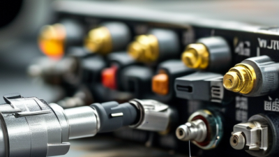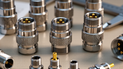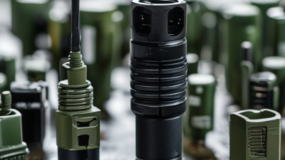
Military connectors are small components with outsized consequences. A loose contact can interrupt power, data, or a sensor signal when vibration and moisture rise. In 2026, the leading choices remain defined less by novelty than by platform needs, qualification, and service life.
MarketsandMarkets’ Military Connectors Market analysis tracks demand by connector type and application, including circular, rectangular, and fiber-optic designs. Its market forecasts are useful indicators, not procurement guarantees; estimates vary with scope and methodology. Grand View Research’s defense-sector coverage also highlights modernization and rising electronic content as market drivers. Neither forecast tells engineers which connector will survive a specific aircraft bay, vehicle hull, or shipboard cabinet.
That decision starts with requirements. MIL-DTL-38999 circular connectors are common where compact, rugged, high-density connections matter. MIL-DTL-5015 types suit some established power and signal interfaces, while rectangular connectors can simplify dense panel layouts. Fiber-optic and RF/coaxial connectors support specialized data and high-frequency paths. Hermetic versions may be needed where pressure boundaries matter. Small parts. Serious consequences.
This guide compares the top military connectors by design, typical use, and trade-offs. It also considers sealing, vibration, contact density, maintainability, and standards compliance. A familiar part number is not proof of suitability. Qualification, materials, and installation details still matter. Public reports rarely show field failure rates or full lifecycle costs, so buyers should verify performance against current specifications and actual operating conditions.
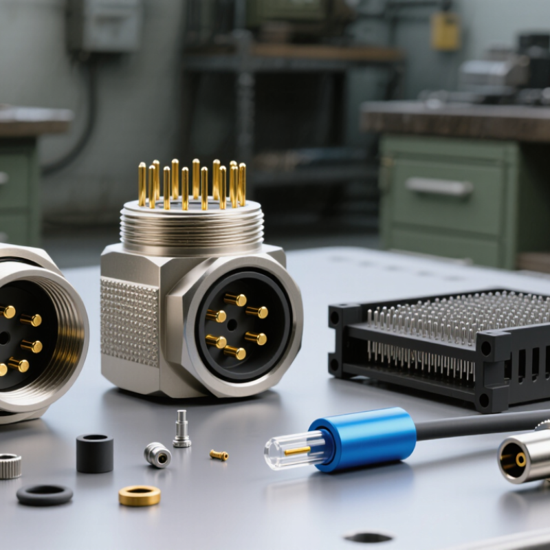
Military connector families solve different interface problems. The right choice depends on signal type, current, space, and exposure. Circular connectors suit equipment panels and field cables where sealing, vibration resistance, and quick coupling matter. Check keying, shell size, contact layout, and sealing requirements carefully. Mismatches can stop work.
Rectangular connectors place many contacts in a compact footprint, making them useful for control units, racks, and removable modules. RF connectors carry high-frequency signals to antennas, receivers, and test points; impedance continuity and shielding are essential. A loose interface can degrade performance. Fiber-optic connectors support high data rates and resist electromagnetic interference, but end-face cleanliness and bend limits require discipline. One speck matters.
Power connectors are selected for current capacity, contact temperature, and safe mating—not pin count alone. Check expected load, wire gauge, environmental sealing, and field serviceability. In practice, packaging constraints can complicate an otherwise neat specification, so teams should verify real installation needs. Hybrid assemblies may combine power and data, but added density can make inspection and repair harder. There is no universal winner.
In 2026, 38999 circular connectors remain a practical choice where equipment faces vibration, moisture, and repeated servicing. The MIL-DTL-38999 qualification benchmark includes 500 mating cycles. That is a test threshold, not a promise that every installed connector will last exactly 500 field connections. The Defense Logistics Agency’s MIL-DTL-38999 performance specification defines the applicable qualification framework; the exact configuration and test conditions matter. Check the relevant specification and qualification records before comparing parts.
Five hundred cycles is substantial. Picture a technician aligning the keyways, engaging the coupling ring, and separating the connector during maintenance. Dirt, side-loading, damaged contacts, or poor handling can change real-world performance. A cycle count alone cannot predict service life. It does, however, offer buyers a repeatable durability reference when comparing qualified configurations. Review contact condition and coupling action during maintenance, and document replacement criteria. This detail is easy to overlook. Qualification results describe tested samples under specified conditions, not every connector in every installation. For a defensible selection, verify the connector’s qualified status and the required cycle count against the current MIL-DTL-38999 documentation.
The stated qualification benchmark is 500 mating cycles. A mating cycle means connecting and disconnecting the connector once; this test-cycle count is not a guarantee of service life in every application.
Rectangular connectors remain common in military electronics because they package many signal paths into a compact, keyed shell. MIL-DTL-24308 defines requirements for D-subminiature connectors, including interface dimensions and performance. The familiar D-shaped metal shell helps prevent incorrect mating. Contact layouts vary by shell size and configuration. Small details matter.
In practice, a panel-mounted receptacle may connect a control unit to a removable cable. The shell secures the connection, while the contacts carry signals between equipment. The specification helps engineers compare compatible configurations, but it does not mean every D-sub connector is interchangeable. Contact count, termination style, mounting hardware, and environmental rating still need checking. A connector may fit and still be unsuitable for vibration, moisture, or repeated servicing.
That distinction is easy to overlook when reviewing a parts list. I would verify the exact configuration and applicable specification revision before approving a replacement. MIL-DTL-24308 is a useful starting point, not a substitute for the equipment’s interface requirements. Field conditions can expose gaps that a drawing does not show. A little caution helps.
MIL-PRF-39012 covers radio-frequency coaxial connectors and related parts used in demanding electrical environments. It defines requirements such as interface dimensions, materials, and performance testing. Common configurations include straight or angled plugs and receptacles. The right choice depends on frequency range, impedance, power, and available space. A connector that fits physically may still introduce unwanted signal loss. Check the applicable detail specification, not just the general standard.
MIL-PRF-29504 addresses fiber-optic termini used in military-style optical connectors. It sets requirements for components that align and hold optical fibers, with performance tied to insertion loss, return loss, and environmental durability. Tiny alignment errors matter. Dust matters, too. A clean end face and correct inspection practices can make a measurable difference. Still, a compliant part alone cannot guarantee a good link; cable preparation and assembly quality also affect results.
Tips: Confirm the exact standard revision and part configuration before ordering. For RF, verify frequency and impedance needs. For fiber, review optical performance limits and cleaning procedures. Test assembled connections under realistic conditions when possible. Paperwork helps, but it can miss a poor fit or a contaminated end face.
For rugged connector systems, an IP67 rating is useful only when its limits are understood. IEC 60529 defines IP67 as dust-tight protection and temporary immersion in water up to 1 metre for 30 minutes under specified test conditions. It does not mean a connector can withstand deeper water, repeated immersion, or every field exposure. A rating is a boundary, not a promise.
The installed details matter. Check whether the rating applies when the connector is mated, capped, or both. A worn seal, grit on the mating face, or a loose coupling can undermine protection. Small details matter. After exposure, inspect the seal and contacts before reconnecting, and follow the connector maker’s care instructions. Salt water, vibration, and changing temperatures can create conditions that a simple immersion test does not represent. That gap is easy to overlook. IP67 is a useful selection reference, but it should sit alongside checks for mechanical fit, cable entry, and the actual environment. A label alone cannot tell the whole story.
Common connector families used in military and defense applications. Selection depends on the equipment, interface, operating environment, and applicable specification; the examples below are not a product ranking.
| Connector Type | Typical Configuration | Common Applications | Relevant Specification Examples | Environmental Considerations |
|---|---|---|---|---|
| Circular, threaded coupling | Multi-contact circular connectors with a threaded coupling mechanism | Aircraft, ground vehicles, shipboard equipment, and field systems | MIL-DTL-38999 | Environmental performance depends on the exact connector design, contact arrangement, accessories, and mated condition. Verify the applicable qualification and sealing requirements. |
| Circular, bayonet coupling | Multi-contact circular connectors secured by a bayonet-style coupling | Portable equipment, vehicles, and other applications requiring quick connection and disconnection | MIL-DTL-26482 | Resistance to moisture, dust, vibration, and other conditions is configuration-specific; the connector family name alone does not establish an IP rating. |
| Circular, general-purpose military | Ruggedized circular connectors available in multiple shell and contact arrangements | Legacy and current equipment across ground, marine, and industrial-military systems | MIL-DTL-5015 | Check the particular insert arrangement, backshell, sealing components, and installation requirements for environmental suitability. |
| Rectangular D-subminiature | Rectangular shells with multiple pin or socket contacts | Control systems, avionics, instrumentation, and electronic equipment interconnections | MIL-DTL-24308 | Environmental protection varies by design and accessories. A standard D-subminiature interface should not be assumed to be sealed against immersion. |
| Fiber-optic military connector | Optical contacts in a ruggedized connector format | High-bandwidth data links, communications, and systems where electrical isolation is useful | MIL-DTL-83526 | Optical performance and environmental sealing are separate considerations. Inspect the specified end-face, coupling, and environmental requirements. |
| RF coaxial connector | Coaxial interface designed to carry radio-frequency signals | Antennas, radios, radar, and other RF equipment | MIL-PRF-39012 | RF performance depends on the specified interface and frequency range. Weather or immersion protection must be verified for the complete installed assembly. |
| Hermetic feedthrough connector | Sealed electrical interface designed to maintain a gas-tight or vacuum boundary | Pressurized enclosures, vacuum systems, and sealed electronic housings | Requirements are typically defined by the equipment and procurement specification | Hermeticity is not the same as an IP rating. Confirm the required leak rate, pressure conditions, and environmental tests separately. |
IP67 clarification: Under IEC 60529, the first digit “6” indicates dust-tight protection. The second digit “7” indicates protection against temporary immersion under the standard’s specified test conditions, commonly described as immersion at 1 m for 30 minutes. IP67 performance applies to the tested enclosure or assembly; it should not be assumed for every connector of a given type, or for a connector while unmated.