Why Use a Board to Board Connector?
A board to board connector links two printed circuit boards without cables, soldered wires, or bulky harnesses. This compact interface supports modular product design, faster assembly, and cleaner internal routing. In a handheld device, it may connect the main logic board to a display, sensor, or power module. In industrial equipment, it can join control boards inside a narrow metal enclosure.
The choice is not merely about saving space. A suitable board to board connector must match the required pitch, current rating, mating cycles, signal speed, and operating environment. As signal-integrity educator Eric Bogatin states, “The connector is part of the channel.” That principle matters when high-speed signals pass through tiny contacts and short electrical gaps. Poor selection can create impedance discontinuities, crosstalk, or intermittent connections. Small parts can cause large problems.
Experience also shows that mechanical details deserve equal attention. Misalignment, vibration, dust, and repeated servicing can reduce reliability. A floating contact system may absorb slight assembly errors, while a rigid design may offer stronger positioning. Neither option is automatically best.
The honest answer is less convenient. A board to board connector does not solve every design challenge. It can increase cost, consume vertical space, and require careful tolerance analysis. Engineers should inspect the complete stack-up, not only the connector drawing. When the application demands modularity, compact routing, and dependable service access, this connector often becomes the practical choice. When those needs are absent, a simpler joint may be wiser.
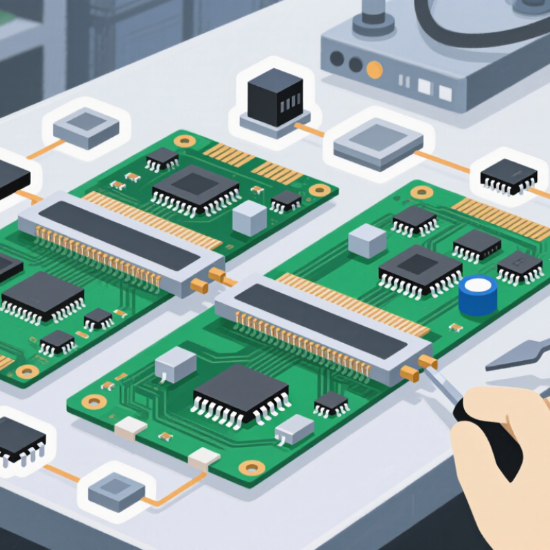
A board-to-board connector is an electromechanical component that joins two printed circuit boards. It transfers electrical signals and power through aligned contacts. Unlike a cable, it keeps the connection inside a compact assembly. Picture two circuit boards stacked like thin shelves. One connector half carries pins, while the other provides matching sockets or contacts. When pressed together, they create a controlled electrical path.
These connectors support parallel, right-angle, and mezzanine board arrangements. They appear in control equipment, communication devices, measurement instruments, and embedded systems. Engineers select them by contact count, pitch, current rating, voltage rating, and mating cycles. Mechanical details matter too. A small guide feature can prevent reversed assembly. A locking structure can reduce movement during vibration. Even a one-millimeter alignment error may damage contacts or interrupt signals.
Real-world inspection remains important. A connector may meet its datasheet limits but perform poorly in a dusty enclosure. Contact plating, insertion force, and temperature exposure deserve careful review. I have found that visual clearance is easy to underestimate near tall components. This is where design assumptions need questioning. Simulation helps, but it cannot replace prototype testing. Measure contact resistance, inspect solder joints, and test repeated mating. Small oversights often appear only after assembly.
Board-to-board connectors join two printed circuit boards without cables. Their basic structure is simple. One half carries contacts, while the mating half receives them. Insulating housings hold each contact at a fixed pitch. This geometry controls alignment, spacing, and electrical distance.
During assembly, one board moves toward another. Guide posts or chamfered openings correct small positional errors. As the connector closes, spring contacts deflect and create normal force. That force maintains a stable metal-to-metal path through vibration and temperature changes. Plated contact surfaces help reduce oxidation and wear. Small gaps matter. They influence impedance, crosstalk, and high-speed signal loss. Power contacts are usually larger, while signal contacts remain compact. Some designs combine both in one connector.
Engineers select a connector by stack height, contact count, current rating, and mating cycles. They also check insertion force and board stiffness. A connector may meet its current rating on paper, yet the finished assembly can run hotter than expected. Thermal testing remains necessary.
In production, coplanarity, solder quality, and housing damage deserve inspection. Microscopes can reveal hidden defects. Alignment is often treated as a minor detail, although it can decide whether a device starts reliably. The design is not flawless. Tight spacing improves density but leaves less room for assembly tolerance. That trade-off needs honest review.
Board-to-board connectors join two printed circuit boards without cables. They save enclosure space and keep signal paths short. In compact control units, that can simplify airflow and service access. The connection feels direct. During prototype work, I have seen engineers reduce wiring errors with guided, keyed interfaces. That practical gain matters when technicians assemble repeated units under time pressure.
Their modular structure supports flexible product design. A main board can connect to a sensor, display, or power board. Designers can select vertical, right-angle, or mezzanine arrangements. Spacing and stack height must match the enclosure. A few millimeters matter. Properly chosen contacts can support stable power delivery and high-speed data transmission. Yet ratings on paper are not enough. Engineers should review current, voltage, mating cycles, vibration, and temperature together. That review improves reliability across real operating conditions.
Board-to-board connectors can reduce assembly time and material use. They also make inspection more focused because fewer loose cables are present. For maintenance teams, detachable boards can shorten replacement work. Still, these connectors are not automatically perfect. Poor alignment may bend contacts or create intermittent signals. I would complete tolerance checks during early layout review, not production. That is an easy lesson to miss. Clearances, support posts, and insertion force deserve measured testing. A connector that fits once may fail after repeated service.
Why Use a Board to Board Connector?
Common Types and Configurations
Board-to-board connectors join printed circuit boards without cables. They save space, support modular layouts, and simplify signal routing inside compact equipment. The right configuration depends on board direction, signal speed, current, and available clearance. Mezzanine connectors place boards parallel, often with a controlled stack height. Right-angle connectors join boards at 90 degrees. Coplanar connectors keep boards on the same plane. Each option solves a different mechanical problem.
Pin-and-socket designs provide reliable mating when alignment is controlled. Floating versions tolerate minor position errors during assembly. Edge-style contacts can reduce parts, but they need accurate board fabrication. Common pitches include 0.5, 0.8, and 1.27 millimeters. Smaller pitches save room, yet they demand tighter manufacturing control. Contact count, plating, insulation material, and mating cycles also affect reliability. A connector may pass electrical tests but still fail after vibration or repeated servicing.
Tips: Confirm the required stack height before routing the boards. Reserve space for insertion tools and inspection. Separate high-current contacts from sensitive signal paths when possible. Check polarization, keying, and retention features early. In prototype reviews, a compact connector often looks perfect on paper. Then assembly access becomes the real problem. Keep it serviceable. I would also test the worst-case alignment, not only the ideal fit. Temperature changes, board flex, and uneven mounting can expose weaknesses that initial measurements miss.
Common configurations support modular assembly, compact stacking, reliable electrical connections, and easier maintenance without cables.
The chart compares nominal contact pitches commonly used in board-to-board connector configurations. Smaller pitches enable higher connection density and more compact PCB layouts, while larger pitches generally provide easier assembly and greater mechanical clearance. Actual specifications vary by connector family, contact count, mating height, and electrical requirements.
Choosing the right board-to-board connector starts with the mechanical layout, not the catalog search. Measure the board spacing, connector height, contact pitch, and available routing area. A connector that fits once may still be wrong. Misalignment can stress solder joints during assembly.
Check the electrical requirements carefully. Confirm rated current, working voltage, contact resistance, signal speed, and impedance control. For a high-speed design, review insertion loss and crosstalk data at the actual operating frequency. Do not rely only on a general “high-speed” label. Also examine the mating cycle rating and contact plating, especially when boards may be serviced repeatedly.
Mechanical stability deserves equal attention. Look for polarization, locking features, guide posts, and tolerance for small board offsets. In a vibration-prone enclosure, a loose friction fit can create intermittent faults. Harsh environments may require stronger retention and suitable temperature or humidity ratings. Test samples with the real boards, screws, and enclosure. A connector may pass a bench test but fail after thermal cycling. That happened because the mounting tolerance was underestimated. It is an easy mistake to repeat.
Read the full datasheet, including derating curves and recommended soldering conditions. Ask for drawings, compliance documents, and test information when specifications seem incomplete. During prototype evaluation, inspect solder fillets, insertion force, and board deflection. Record the results. Good selection is not only about electrical performance; it is about predictable assembly, maintenance, and long-term contact reliability.
| Connector Category | Typical Pitch | Typical Board Spacing | Typical Current per Contact | Typical Mating Durability | Signal Suitability | Recommended Applications | Key Selection Checks |
|---|---|---|---|---|---|---|---|
| Standard Mezzanine Connector | 0.80–2.54 mm | 5–20 mm | 0.5–3 A | 50–500 cycles | General digital signals; moderate-speed interfaces | Embedded control boards, industrial electronics, instruments | Pin count, board spacing, alignment, voltage rating, and available PCB area |
| Fine-Pitch High-Density Connector | 0.35–0.80 mm | 3–12 mm | 0.2–1.5 A | 30–200 cycles | High-density digital signals and compact differential pairs | Portable devices, compact computing hardware, space-constrained products | Assembly tolerance, coplanarity, insertion force, inspection method, and mechanical support |
| High-Speed Differential Connector | 0.50–1.27 mm | 5–25 mm | 0.3–2 A | 50–250 cycles | High-speed serial links when impedance and crosstalk are controlled | Networking equipment, storage systems, test equipment, high-speed computing | Differential impedance, insertion loss, return loss, skew, crosstalk, and via design |
| Power-Oriented Board-to-Board Connector | 1.27–5.08 mm | 5–30 mm | 3–30 A | 30–200 cycles | Power distribution and low-to-moderate-speed signals | Power modules, battery systems, motor control equipment, industrial assemblies | Temperature rise, contact resistance, current derating, creepage, clearance, and heat dissipation |
| Right-Angle Board-to-Board Connector | 0.80–2.54 mm | Varies by layout; commonly 5–20 mm | 0.5–5 A | 50–500 cycles | General signals; high-speed performance depends on geometry | Folded assemblies, backplanes, compact enclosures, and perpendicular PCBs | Board orientation, retention, mating direction, enclosure clearance, and cable access |
| Floating or Self-Aligning Connector | 0.50–2.00 mm | 5–20 mm | 0.5–5 A | 50–300 cycles | General and selected high-speed applications | Assemblies with positional tolerances, vibration, or multiple connector interfaces | Permitted float, alignment range, vibration resistance, retention force, and tolerance stack-up |
| Shielded or EMI-Controlled Connector | 0.80–2.54 mm | 5–25 mm | 0.5–3 A | 30–300 cycles | High-speed or noise-sensitive signals requiring controlled shielding | Medical electronics, communication equipment, measurement systems, and industrial controls | Shield continuity, grounding strategy, contact wipe, signal reference, and enclosure integration |
Note: The values shown are representative design ranges rather than universal ratings. Actual performance depends on contact geometry, plating, PCB layout, operating temperature, airflow, mating conditions, and the manufacturer's electrical and mechanical specifications.