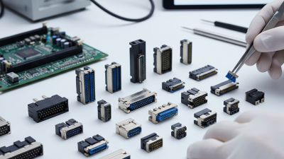
Choosing amphenol military connectors is not just a matter of matching pin counts. The right choice depends on the equipment, installation space, operating environment, and maintenance plan. A connector mounted beside a vibrating engine faces different demands from one inside a protected communications cabinet. Small details matter: shell size, contact layout, coupling style, sealing, and cable compatibility. A mismatch can complicate assembly or make field replacement harder.
Quality-management expert W. Edwards Deming said, “In God we trust; all others must bring data.” His advice is useful here: compare documented requirements with the connector’s rated performance, rather than relying on appearance or a familiar part number. Review the applicable product drawings and specifications, then confirm environmental, electrical, and mechanical requirements with the supplier or a qualified engineer. Product families can look similar. They are not automatically interchangeable.
There is no perfect connector for every installation. Trade-offs remain. A compact design may simplify packaging but leave less room for handling during service. This guide outlines how to assess application needs, compare key specifications, and verify compatibility before ordering. It also considers sourcing and lifecycle support, because a suitable part is only useful if it can be maintained. One detail is easy to overlook: confirm the exact configuration, not just the series name.
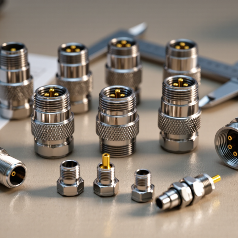
Map the mission before selecting a connector. Start with the route. Record temperature extremes, humidity, water exposure, dust, vibration, and shock at the installed location. A vehicle bay, exposed mast, and portable case create different stress patterns. Use operating logs or site measurements when available; assumptions can miss short, severe events.
Choose relevant MIL-STD-810H methods and tailor their procedures to the equipment’s real conditions. Methods 501.7 and 502.7 address high and low temperatures; 507.6 covers humidity. For vibration and mechanical shock, review 514.8 and 516.8. Methods 506.6, 510.7, and 521.4 may apply to rain, dust, or icing. Test the assembled interface. Include the connector, backshell, cable, sealing parts, and mounting hardware, not just a loose component. Specify whether it is mated, energized, or exposed during each test. Then inspect for water ingress, loosened coupling, damaged seals, and electrical interruptions. A tidy test matrix can still overlook maintenance handling or worn seals. That is worth revisiting before setting acceptance limits. MIL-STD-810H methods guide tailored testing; they do not, by themselves, prove suitability for every mission.
When choosing a MIL-DTL-38999 connector, treat 500 mating cycles as a useful comparison point, not a universal guarantee. Cycle life can vary by connector configuration, contact arrangement, and qualification conditions. Check the product documentation for the exact tested configuration and whether 500 cycles refers to mating and unmating under specified conditions. A rating alone may not reflect your installation.
Consider how the connector will be handled in service. Frequent inspections, hurried alignment, or grit around the coupling threads can increase wear. Look for clear guidance on coupling, contact replacement, and inspection intervals. Small details matter. A connector that mates smoothly on a clean bench may behave differently in a vibrating enclosure exposed to moisture or dust. Confirm that the selected shell size, insert arrangement, and accessories suit the actual environment.
If your equipment will be disconnected often, compare cycle-life evidence across candidate configurations and include a margin above expected use. For example, 500 planned mating cycles leave little room for rework or maintenance connections. Track real use during trials, and inspect contacts and coupling parts for damage. Test results are helpful, but field conditions are rarely perfect.
| Series | Coupling Style | Typical Selection Strength | Selection Considerations | 500-Cycle Benchmark Check | Best-Fit Use Case |
|---|---|---|---|---|---|
| Series I | Bayonet coupling | Quick connect and disconnect with a positive bayonet-locking action. | Consider the space required for coupling and the need for a fast, deliberate connection. | Use 500 cycles as the acceptance target. Confirm the endurance rating for the exact qualified connector configuration. | Applications needing quick mating and a secure coupling, such as equipment that is connected or serviced regularly. |
| Series II | Bayonet coupling with a low-profile interface | Designed for applications where a lower-profile connector interface is useful. | Check available clearance, the specified shell and insert arrangement, and the applicable detail specification. | Do not infer cycle life from the series name alone. Verify that the selected part is qualified for at least 500 mating cycles. | Installations where connector profile and access are important alongside quick bayonet coupling. |
| Series III | Threaded coupling | Threaded engagement provides a secure connection when properly mated. | Allow room and time for coupling rotation; confirm the required environmental, contact, and accessory options. | Compare the exact part’s documented mating endurance with the 500-cycle target before selection. | Applications prioritizing threaded coupling and secure engagement over the fastest connect-and-disconnect action. |
| Series IV | Breech-lock coupling | Quick connect and disconnect through a breech-lock mechanism. | Check compatibility with the required mating interface and verify the specific qualified configuration. | Treat 500 cycles as a part-level verification requirement, not an assumed rating for every configuration. | Applications requiring rapid connection and disconnection using a breech-lock interface. |
| How to apply the benchmark: One mating cycle means one complete mating and unmating operation. A 500-cycle target is a comparison threshold, not a guarantee of service life in the field. Confirm the endurance rating and qualification evidence for the exact connector part, insert arrangement, and applicable detail specification; mating life does not by itself establish resistance to vibration, corrosion, temperature, or other environmental conditions. | |||||
Choose contacts by checking the published current, voltage, and wire-gauge ratings for the exact connector configuration. Do not rely on a family-level summary when the datasheet lists different limits by contact size. A contact rated for a particular current may require a specific wire gauge and operating temperature. Check all three ratings together. Then consider how many contacts will carry current at once. Closely packed, fully loaded contacts can run warmer than a single-contact test suggests. The published rating is a starting point, not a promise for every installation.
Match the wire gauge to the contact’s approved range, and confirm that the termination method suits the wire construction. Verify the circuit’s maximum voltage, including expected transients, against the rated limit. Leave margin when the equipment faces heat, vibration, or continuous heavy loads. Small details matter. A wire that fits physically may still fall outside the specified range. It is tempting to choose the highest current figure and move on, but that shortcut can miss temperature and bundling effects. Review the manufacturer’s test conditions and ask a qualified connector engineer when the application differs from them. Real installations are imperfect; document assumptions and recheck them during design reviews.
Selecting military connectors for EMI control starts with the test, not the catalogue. The U.S. Department of Defense’s MIL-STD-461G defines CE102 conducted-emissions testing from 10 kHz to 10 MHz and RE102 radiated-emissions testing from 10 kHz to 18 GHz. These ranges show why one shielding claim cannot cover every installation. The standard evaluates equipment and subsystems in specified configurations; a connector alone does not establish compliance.
Inspect the full shielding path: connector shell, backshell, cable braid, and the panel bond. A shiny shell can still leak at a poorly terminated braid. Check contact resistance, shell continuity, and whether the mating interface maintains circumferential contact after vibration. Also confirm that test limits and procedures match the platform’s applicable requirements. MIL-STD-461G limits can vary with frequency and test setup, so avoid treating a single attenuation figure as proof. I would verify the assembled cable-and-enclosure configuration before final selection; connector datasheets rarely capture every installation detail.
Tips: Ask for test data covering the intended frequency range and configuration. Check the backshell termination closely. Small gaps matter.
MIL-STD-461G test methods cover different frequency ranges. Use this chart to identify relevant conducted and radiated EMI tests when evaluating a connector and its assembled cable system. The ranges are test coverage—not connector pass/fail limits or a guarantee of performance.
Frequency ranges shown: CE102, 10 kHz–10 MHz; CS114, 10 kHz–200 MHz; CS116, 10 kHz–100 MHz; RE102, 10 kHz–18 GHz; RS103, 2 MHz–18 GHz. Applicable limits and test setup depend on the equipment, platform, and standard tailoring. Confirm EMI performance on the fully assembled connector, backshell, cable, and enclosure.
Before selecting a military connector, confirm that its qualification matches the conditions it will actually face. Check the exact part number, shell size, contact layout, and termination style against the qualification record. A connector family may include versions with different ratings. Do not assume one test report covers them all. Review temperature, vibration, moisture, and sealing requirements, then check the document revision and any stated limits. A rating is only useful when it applies to the complete configuration.
Keying details deserve equal care. Compare the connector’s keyway position with the mating half and the assembly drawing; a visual match can still hide a mismatch. Check pin assignments before wiring. Small errors matter. Installation data should specify panel cutout dimensions, mounting torque, wire range, strip length, crimp tooling, and backshell clearance. Confirm the required sealing parts and cable bend radius, too. A connector may fit the panel yet leave too little room for the harness. Where possible, trial the specified parts in a representative assembly and inspect access for tools. Paper checks help, but they do not catch every awkward installation detail. Recheck the latest drawings before release.