
8 Essential Tips for Choosing M8 Connectors?
Choosing the right m8 connector can determine whether a sensor network remains stable or fails during daily operation. In factory environments, connectors face vibration, oil mist, moisture, temperature changes, and repeated maintenance. Small details matter. A connector that fits perfectly on a workbench may loosen beside a moving conveyor. This guide presents eight practical tips for evaluating thread size, pin configuration, coding, current rating, protection level, shielding, cable compatibility, and installation requirements.
The best choice begins with the application, not the product photograph. Check the equipment datasheet, wiring diagram, and manufacturer specifications before ordering. An IP rating may describe water resistance, but it does not automatically confirm resistance to chemicals or continuous vibration. Confirm operating temperature, mating cycles, conductor size, and material quality. For industrial Ethernet or sensor signals, shielding and correct coding can prevent interference and costly wiring errors. A right-angle design may save space, while a straight version can simplify cable routing. Neither option is universally better.
Real-world testing also deserves attention. Inspect the locking thread, gasket, contacts, and cable jacket after installation. Measure the available clearance with the machine fully assembled. This step is often missed. Reliable suppliers should provide clear drawings, test data, traceability, and responsive technical support. However, no checklist replaces application-specific validation. Even experienced engineers can overlook a connector’s bend radius or strain relief. These eight tips offer a practical starting point, while careful verification protects performance, safety, and long-term maintenance costs.
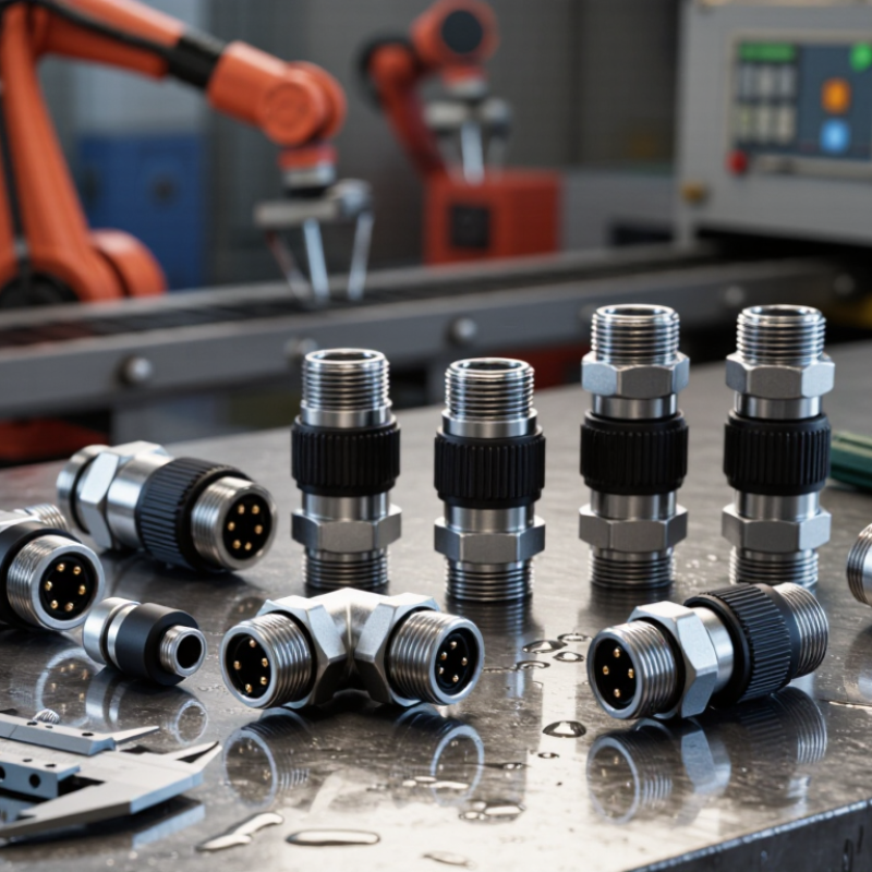
Table of Contents
[Hide]
Define M8 Connector Types and Their Common Applications
M8 connectors use an 8 mm threaded coupling system for compact, secure electrical connections. Their small body suits tight control cabinets, robotic arms, and machine sensors. Common versions include male and female connectors, straight or right-angle bodies, and field-wireable or pre-molded cables.
Pin arrangements can include three, four, five, or eight contacts. Each configuration supports different signals, such as power, switching, analog measurement, or data communication. Do not assume that every four-pin M8 connector shares the same wiring. Check the pin assignment, voltage rating, current capacity, and coding before installation. Size matters.
M8 connectors appear in proximity sensors, photoelectric sensors, valve controls, encoders, and compact industrial networks. Unshielded types often suit simple sensor circuits, while shielded designs can reduce interference near motors and drives. Right-angle versions help protect cables from sharp bends and moving equipment. In outdoor or washdown areas, verify the stated IP rating after mating. A sealed connector can still fail when its cable jacket is damaged. That detail is easy to miss.
Choosing the correct connector also requires attention to temperature, vibration, cable flexibility, and mating cycles. A threaded connection usually resists vibration better than a friction-fit design, but overtightening may damage the coupling threads. The practical lesson is imperfect: connector selection is not only about pin count. Confirm the complete assembly, including cable material, mounting space, and the equipment’s wiring diagram.
8 Essential Tips for Choosing M8 Connectors? - Define M8 Connector Types and Their Common Applications
| No. | Selection Dimension | M8 Connector Type or Specification | Typical Characteristics | Common Applications |
|---|---|---|---|---|
| 1 | Confirm the M8 interface | M8 circular threaded connector | The mating thread is nominally 8 mm; the connector is commonly defined under IEC 61076-2-104. Pin count, coding, mounting style, and electrical ratings still need to be specified. | Compact sensors, actuators, instrumentation, and space-constrained industrial equipment. |
| 2 | Select the coding | A-coded, B-coded, C-coded, D-coded, or X-coded | Coding keys help prevent incorrect mating between incompatible circuits. Coding availability and pin assignments can vary by connector design. | A-coded: sensors and actuators; B-coded: selected fieldbus or industrial control systems; D-coded: industrial Ethernet; C-coded and X-coded: specialized power or high-speed designs. |
| 3 | Match the contact count | 3-, 4-, 5-, 6-, or 8-contact configurations | Four-contact versions are widely used for basic sensor signals. More contacts support additional signals, supply lines, or communication functions. | Proximity sensors, photoelectric sensors, pressure sensors, valves, switches, and compact I/O devices. |
| 4 | Check the signal or network requirement | D-coded M8 Ethernet connector | Typically uses four contacts for industrial Ethernet links commonly rated up to 100 Mb/s. Confirm the cable category, shielding, impedance, and transmission specification. | Industrial Ethernet sensors, compact controllers, remote I/O, machine vision equipment, and robotic systems. |
| 5 | Verify voltage and current ratings | Signal, sensor, or power version | Ratings depend on contact size, insulation, pin count, ambient temperature, cable size, and applicable standard. Do not infer the rating from the M8 size alone. | Low-power sensors, control signals, small actuators, and compact DC power connections. |
| 6 | Choose the environmental protection | IP65, IP67, or IP68 versions | IP ratings describe protection against dust and water under defined test conditions. The fully mated connector, cable, panel interface, and sealing system must be considered together. | Factory automation, outdoor equipment, washdown areas, packaging machinery, and mobile industrial systems. |
| 7 | Evaluate mechanical installation needs | Field-wireable, molded cable, panel-mount, or right-angle design | Consider cable exit direction, available clearance, mounting thread, locking method, bend radius, vibration, and mating cycles. | Robotic arms, conveyor systems, control cabinets, machine frames, sensors, and modular automation equipment. |
| 8 | Confirm materials and compliance | Metal or engineered-polymer housing; shielded or unshielded cable | Check contact material and plating, insulation material, cable jacket, operating temperature, chemical resistance, EMC shielding, flammability, and required regional compliance. | Food and packaging machinery, factory floors, high-noise environments, temperature-variable systems, and general industrial automation. |
Practical selection note:
M8 connector ratings are design-dependent. Always verify the applicable datasheet for pin assignment, rated voltage, rated current, temperature range, IP protection, cable compatibility, shielding, and mating requirements before installation.
Related Posts
-
How to Choose the Right M8 Connector for Your Needs?
-
2026 Best M8 Connector Options for Global Buyers?
-

What is Amphenol Cable and How Does it Work?
-

How to Choose the Right Industrial Connectors for Your Needs?
-
China Best Wire to Board Connector Manufacturers?
-
Top Amphenol 4 Pin Connector Uses Benefits and Applications?